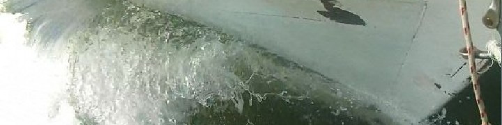

Stationary smoke wall shows the tip vortices as well as the downwash created by the passage of a lifting foil.
Induced drag , or vortex induced drag is a topic one often hears mentioned at the technical end of sailing enthusiast circles.
Induced drag is the energy cost of lift.
In this post I’ll elaborate a bit on the post of ‘How is lift made‘ of two weeks back as well as to lay some groundwork in place that will be useful in future posts that will attempt to correct some commonly held fallacies as to some of the implications of induced drag.
As i explained in the penultimate post, lift is produced by creating a pair of counter rotating vortices; one that is shed at the starting point, and one that is bound by the wing and travelling along with it. These vortices are created by the act of moving an inclined plane or streamlined plane through a fluid.
What i neglected to mention is that a free flying wing must have ends; i.e. it cannot be infinitely long. So what happens at the ends of the wing?
Since there is by definition a pressure difference across the thickness of any lifting wing (otherwise it would not be lifting!) , when one gets close to the ends, the higher pressure underneath tends to push the streamlines out towards the free area beyond the wing tip, and similarly, the lower pressure above the wing tends to pull in air from beyond the tip. Both of these together make the air curl around the end of the lifting foil, at the same time that the fluid particles are flowing aft. When looking at the streamlines it looks like they get twisted up around the tip of the wing. They carry on twisting behind the wing under the newly acquired momentum, forming a long contiuous vortex going back along the path of where the wing came.

Tip vortex streamlines
Kutta and Joukowski both discovered and defined the concept of circulation;

Now, Helmholtz’s theorems, state that a vortex can never start or end within the fluid, apart from instantaneously when being formed; instead any vortex must either join up with itself forming a loop without ends, or terminate at a fluid boundary.
Putting this together, we realize that the circulation vortex that bounds the wing and the vortices being shed off the wings are one and the same. Then, remembering that a vortex cannot have an end, we follow these tip vortices back all the way to where the wing began its journey,… and where it left behind its starting vortex, and there, the tip vortices join up with the ends of the starting vortex.
So we see that there is no ‘end’, it is all actually one continuous rectangular vortex. One short side is where the trailing edge of the wing was at the beginning, the two longer, and continually lengthening, sides are the lines the wingtips traced out in space, and finally the other short side goes through the wing from tip to tip and moves along with it. This last is the “bound” vortex part of the total rectangular vortex ring, and the part that is actually creating the lift which is the always manifested by the moving of a bound vortex through the fluid.
Around the outside of this rectangle air is moving up, and within it is moving down. This downwards moving air is the air that the passage of the foil forced downwards, called the downwash.
Not only do the tip vortices not contribute any useful lift they took energy to create so represent lost energy for the plane. Also, the ‘spillage’ of air from the tip makes the foil less effective at accelerating air downwards, so represents a loss of lift too.

Lift distribution and trailing vortices
source; Olivier Cleynen

The anatomy of a wing rectangular vortex wake .
So how does this tip vortex create the extra resistance?
It actually does not, at least not directly, what it does instead is induce the resistance by affecting the overall airflow over the wing. Think about this; the extra downwash attributable to the tip vortices does not contribute to lift, yet is causing air to sink more than if there were no tips ‘leaking’. This in turn means that the foil is continually forced to climb out of the hole it is creating for itself. Since lift is produced at right angles to the airflow and this airflow is pivoted downwards it means the lift force is rotated aft as compared to the direction normal to the axis of travel. This creates a component of the lift force to be adding itself to the rest of the drag.

Downwash induced by the tip vortices negatively affect the orientation of the lift vector.
Now to quantize some of these concepts…
I will spare readers the full derivation of these equations, and just jump straight to the conclusions. For those interested in knowing more, wikipedia has a surprisingly thorough amount of information on this.
The Coefficient of lift of a foil is defined in the following dimensionless manner;
.

Where F is the lift force produced, 

And the coefficient of induced drag works out to be;
.

Where 
.

where b is the span of the foil from tip to tip. 
So we see that the longer and skinnier (higher aspect ratio) the lower the induced drag. Also the lower the

Leave a comment
Comments feed for this article